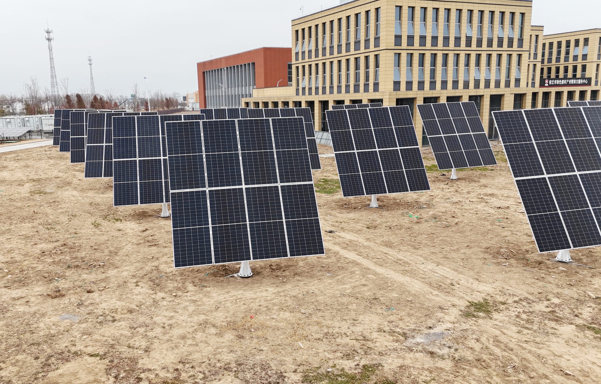
TG-8 V3 Solar Tracking Racking

TG-8 V3 Dual-Axis Solar Tracker · Interactive 3D Demo

Eight scenes explain one single-column dual-axis solar tracker: 8 × 640–665 W PV modules with a rated capacity of 5.12–5.32 kWp, azimuth slew plus tilt actuator, 91 original CAD parts in 12 assembly groups, an SE7A slew drive, a Y817W tilt actuator and a symmetric pair of dampers, closing on an exploded view of the whole machine.

01 Overview

TG-8 V3

Our in-house solar tracking racking is different from fixed racks and single-axis trackers. It adjusts azimuth and tilt at the same time, keeping the modules at the best angle to the sun all day. Load-bearing structure, dual-axis drive, position feedback, control strategy, safety protection and cloud O&M make up six parts that work together as one complete solar tracking system.

PV modules carried
8pcs
Energy yield gain
30%↑
O&M cost reduction
80%↓
  • Module array8 × 640–665 W · 5.12–5.32 kWp
  • Column & baseslew plane at 2.22 m
  • Slew driveSE7A · horizontal C-type

02 Dual-Axis Tracking

Azimuth Slew + Tilt Actuator

Powered by the SmartTrack™ 3.0 tracking algorithm: astronomical calculation and edge computing work together to stay locked on the sun's path; local irradiance and weather data correct the aim in real time, and tracking continues even under overcast diffuse light, with no grid power needed. Average annual yield is up 30%, and the winter peak gain can exceed 50%.

Tracking accuracy
±0.5°
Azimuth slew
±180°
Tilt travel
0–70°

03 Slew Drive Assembly

Slew Drive Assembly

The slew mechanism ties drive, reduction and bearing support together on the azimuth axis, turning the upper array horizontally to follow the sun's azimuth angle.

Slew drive
SE7Ahorizontal C-type
Demo azimuth range
±35°
Slew plane height
2.22m
  • Slew driveSE7A · drive · reduction · bearing

04 Tilt Actuator

Tilt Actuator

An electric linear actuator (Y817W) applies axial thrust to the main beam through its hinge point, tilting the module array about the elevation axis. Two symmetric dampers absorb wind-induced vibration and let the tilt motion settle smoothly.

Actuator model
Y817Wseries
Installation length
800–1100mm
Layout
1centred
  • Electric actuatorY817W · hinged tilt drive

05 Mechanical Dampers

Dampers

2 dampers (S30-535QQ) are arranged symmetrically on sides A/B, helping to control transient disturbance and motion oscillation. A velocity-dependent damping force dissipates kinetic energy, softening the dynamic shock transmitted to the main beam, hinge points and drive train.

Damper model
S30series
Quantity
2sets
Layout
A / Bsymmetric
  • Mechanical damper2 sets · A/B symmetric

06 Extreme Conditions

Extreme Weather Protection

Cloud early warningAuthoritative weather data looks 72 hours ahead at severe conditions so protection can be staged in advance.

Edge fast responseOn-board sensors monitor at millisecond resolution and automatically trigger high-wind and heavy-snow protection modes.

Hardened hardwareLevel-12 wind rating, reinforced snow load, wide-temperature components and three-stage lightning protection.

07 Global Smart Cloud Platform

Global Smart Cloud Platform

See the whole fleet on the desktop dashboard, check it anywhere from the App, with monitoring and control in one place. Equipment, generation, alarms and control cover the full plant O&M workflow and cut blind site inspections.

08 Exploded View

Structure, exploded

Twelve factory groups stack up above the fixed column: the slew housing and its motor, the slew output and its bolted ring, the upper mast and stays, the main beam with its tilt stops, the module frame with its clamps, the edge clamps, then the eight modules. The actuator, the two damper sets and the control box lift off to the sides. Every group ships pre-assembled — on site the machine bolts together around the column.

Major assemblies
12groups
Original CAD parts
91pcs
Fasteners & joints
52pcs
  • Fixed columnfixed assembly · limit stops
  • Slew driveSE7A-57MHD · azimuth axis
  • Module array8 × 640–665 W · 5.12–5.32 kWp
  • Tilt actuatorY817W-260328A1 · hinged to the sail
Global Smart Cloud Platform · TG-8 V3 5G

Linked trackerAuto-linked

Sun azimuth
--°
Sun elevation
--°
Tracker azimuth
--°
Tracker elevation
--°

Today's PV power--

0006121824

Loading model 0%

Engineering, Made Visible

Advantage, hidden in every connection.

From array capacity down to every joint — each figure traces back to real structure and ledger records.

TG-8 V3 eight-module array, front view
5.12–5.32 kWp

Eight modules, capacity at a glance.

A 2×4 layout takes 640–665 W modules for 5.12–5.32 kWp STC — array size and module choice in one view.

TG-8 V3 tilt actuator and slew drive tower, rear close-up
slew + actuator

Two axes, each doing its own job.

Azimuth comes from the slew drive, tilt from the actuator — every dual-axis move maps to a real mechanism, not a stand-in animation.

TG-8 V3 damper close-up
2 units / 1.0–9.0 kN

Twin dampers keep the face steady.

Two symmetric dampers span 1.0–9.0 kN across 0.02–0.66 m/s, settling the array face as speed builds.

TG-8 V3 limit switch close-up
4 limit switches

Four limits, travel bounds on record.

Limit switches, flags and brackets sit in the original assembly — travel bounds and protective poses documented, not assumed.

TG-8 V3 slew drive and actuator close-up
57 : 1 / 1,596 N·m

External drive, ratings stated with clarity.

SE7A slew drive and Y817W actuator sit in the same assembly: output 1,026 N·m normal / 1,596 N·m peak through a 57 : 1 drive — assembly figures, not motor-shaft values.

TG-8 V3 frame connection node: brace pins and bolted joints
as drawn

How it bolts together is on the drawing.

Clamps, hoops, pins and bolts each carry a part number and an installation position on the assembly drawing — crews build to it, inspection checks against it.

Application Scenes

Any terrain, any climate.

Pile-mounted and self-adapting to the ground, it chases the light on any terrain: mountains, islands, farmland or business parks.

Dual-axis tracker at a mountain power plant
Mountain plantRugged terrain, still squared to the sun. Slope and orientation adapt automatically so every module faces the light.
TG-8 V3View specs ›
Dual-axis tracker in an off-grid island scene
Off-grid islandOff the grid, still a steady daytime supply. Working with storage, it widens the off-grid power window.
TG-8 V3View specs ›
Dual-axis tracker in an agrivoltaic scene
AgrivoltaicsPower above, farming below. Pile foundations take little ground, so generation and cultivation coexist.
TG-8 V3View specs ›
Dual-axis tracker in a business park
Business parkInstall it on the green and go. The column-mounted design blends naturally with the surroundings.
TG-8 V3View specs ›
Technical specifications

TG-8 V3 technical specifications

TG-8 V3 belongs to HELIO² 双轴跟踪支架; other models in the series can be compared on the series overview page.

Model

Model
TG-8 V3 Single-slew + single-actuator solar tracking racking
Ordering model
TG-8 V3 WZPV-SZTZ-8
Module count
TG-8 V3 8 modules
  • 8 positions, 2 × 4 layout
  • PV modules are not included in the racking supply
DC nominal capacity
TG-8 V3 5.12–5.32 kWp
  • 8 × 640–665 W modules (STC nameplate total)

Tracking performance

Tracking range
TG-8 V3 Azimuth ±180° rotation / tilt 0–70° swing Both axes are driven independently; azimuth and tilt operating ranges can be set separately

Drive architecture

Drive architecture
TG-8 V3 Single-column dual-axis · 1 azimuth slew + 1 rear actuator
Mechanical architecture
TG-8 V3 1 azimuth slew / 1 rear actuator / 2 mechanical dampers Azimuth slew: SE7A-57MHD-24HRC-1202 Rev.C, 1 unit Rear actuator: HB-DJ817W / Y817W-260328A1, 1 unit Mechanical dampers: S30-535QQ-BE12-20260326, 2 units
Slew output torque
TG-8 V3 Normal 1,026 N·m / max. 1,596 N·m (up to 3 s) Assembly-level values, not motor-shaft figures
Overturning moment
TG-8 V3 Tilting moment 7,000 N·m / holding moment 13,500 N·m Axial / radial rated load 34 / 58 kN
Gear ratio / output speed
TG-8 V3 57 : 1 / 0.02 rpm
Actuator stroke
TG-8 V3 300 ± 3 mm Minimum installation centre distance 800 ± 3 mm
Actuator dynamic / static load
TG-8 V3 Max. dynamic load 25 kN per unit / conditional static load 50 kN (half stroke)
Drive power supply
TG-8 V3 24 V DC matched drive Actuator max. current 5 A, duty cycle ≤ 10 %
Damper piston speed
TG-8 V3 0.02 – 0.66 m/s
Reference damping force
TG-8 V3 1.0 – 9.0 kN 0.02 m/s: 1,000 N 0.20 m/s: 4,000 N 0.50 m/s: 7,500 N 0.66 m/s: 9,000 N

Structural protection

Enclosure protection
TG-8 V3 Slew drive IP66 / −40 to +80 °C Actuator IP66 / C3 corrosion class / −20 to +60 °C
  1. A "—" means the item does not apply to that model, or must be issued separately against the approved project drawing and structural calculation report; ratings and dimensions are model-specific.
  2. DC nominal capacity is derived from the module count and module power in this table; it is not an instantaneous guaranteed output, nor does it equal annual energy yield.
  3. Class 12 is a design rating under the specified protective posture, project foundation and installation conditions, and does not mean normal operation in Class 12 winds; mechanical damping is dynamic cushioning, not static load bearing, and does not add up to a wind-resistance rating.
  4. Dimensions are in mm; specifications on this page are subject to the final order and project documents.