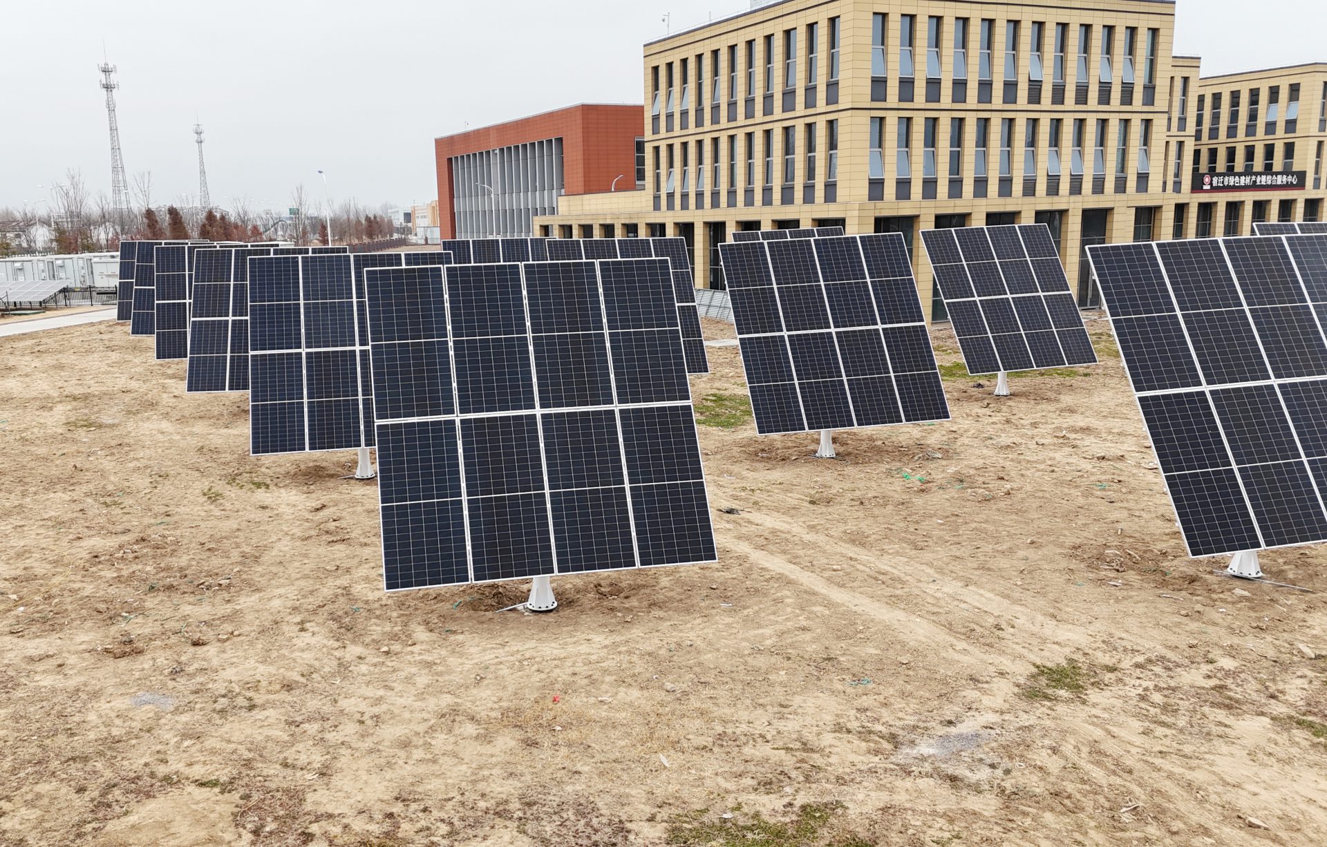

TG-24 Dual-Axis Solar Tracker · Interactive 3D Demo
Eight scenes explain one dual-axis solar tracker: 67.6 m² of light-collecting area per unit, a 6.91 × 10.00 m sail, a 3.02 m column, ±180° azimuth slew and 0–70° tilt travel, 632 parts, 8 major assemblies and 37 interlocking constraints, closing on an exploded view of the whole machine.
01 Overview
TG-24
Our in-house solar tracking racking is different from fixed racks and single-axis trackers. It adjusts azimuth and tilt at the same time, keeping the modules at the best angle to the sun all day. Load-bearing structure, dual-axis drive, position feedback, control strategy, safety protection and cloud O&M make up six parts that work together as one complete solar tracking system.
- PV modules carried
- 8-24pcs
- Energy yield gain
- 30%↑
- O&M cost reduction
- 80%↓
- Tilted sail6.91 × 10.00 m
- Column & base flange3.02 m / 0.63 m
- Slew reducerSDE17A
02 Dual-Axis Tracking
Azimuth Slew + Tilt Actuator
Powered by the SmartTrack™ 3.0 tracking algorithm: astronomical calculation and edge computing work together to stay locked on the sun's path; local irradiance and weather data correct the aim in real time, and tracking continues even under overcast diffuse light, with no grid power needed. Average annual yield is up 30%, and the winter peak gain can exceed 50%.
- Tracking accuracy
- ±0.5°
- Azimuth slew
- ±180°
- Tilt travel
- 0–70°
03 Slew Drive Assembly
Slew Drive Assembly
The slew mechanism ties drive, reduction and bearing support together on the azimuth axis, turning the upper array horizontally to follow the sun's azimuth angle.
- Max output torque
- 24,480N·m
- Gear ratio
- 102:1
- Rated output speed
- 0.016r/min
- Slew mechanismSDE17A · drive · reduction · bearing
04 Dual Actuators
Dual Actuators
Two electric linear actuators apply axial thrust to the tilt mechanism through their hinge points. Dual Hall sensors feed stroke detection and coordinated control, reducing off-centre loads and the risk of abnormal operation.
- Max dynamic load
- 25kN
- Conditional static load
- 50kN
- Stroke
- 300mm
- Electric actuatorStroke 300 ±3 mm
05 Mechanical Dampers
Dampers
8 dampers are distributed across the connections, helping to control transient disturbance and motion oscillation. A velocity-dependent damping force dissipates kinetic energy, softening the dynamic shock transmitted to the load-bearing structure, hinge points and drive train. Together with active drive, limit protection and high-wind strategy they keep the unit running smoothly.
- Piston speed 0.20 m/s
- 4.0kN
- Piston speed 0.66 m/s
- 9.0kN
- Distributed connections
- 8sets
- Mechanical damper8 sets · distributed
06 Extreme Conditions
Extreme Weather Protection
Cloud early warningAuthoritative weather data looks 72 hours ahead at severe conditions so protection can be staged in advance.
Edge fast responseOn-board sensors monitor at millisecond resolution and automatically trigger high-wind and heavy-snow protection modes.
Hardened hardwareLevel-12 wind rating, reinforced snow load, wide-temperature components and three-stage lightning protection.
07 Global Smart Cloud Platform
Global Smart Cloud Platform
See the whole fleet on the desktop dashboard, check it anywhere from the App, with monitoring and control in one place. Equipment, generation, alarms and control cover the full plant O&M workflow and cut blind site inspections.
08 Exploded View
Structure, exploded
The machine comes apart into its assembly groups: base column and foundations, azimuth ring, slew drive, tilt sail, module clamps and the PV array separate along the mast, while the two actuators and eight dampers lift off to the sides. Every group ships pre-assembled — on site the whole machine bolts together around the column.
- Major assemblies
- 8groups
- Original CAD parts
- 632pcs
- Interlocking constraints
- 37sets
- Base columnfixed assembly · foundation flange
- Slew driveSDE17A · azimuth axis
- PV arraymodules on rails
- Tilt actuatorY817W · hinged to the sail