
SZGZ-X Dual-Axis Solar Tracker · Interactive 3D Demo
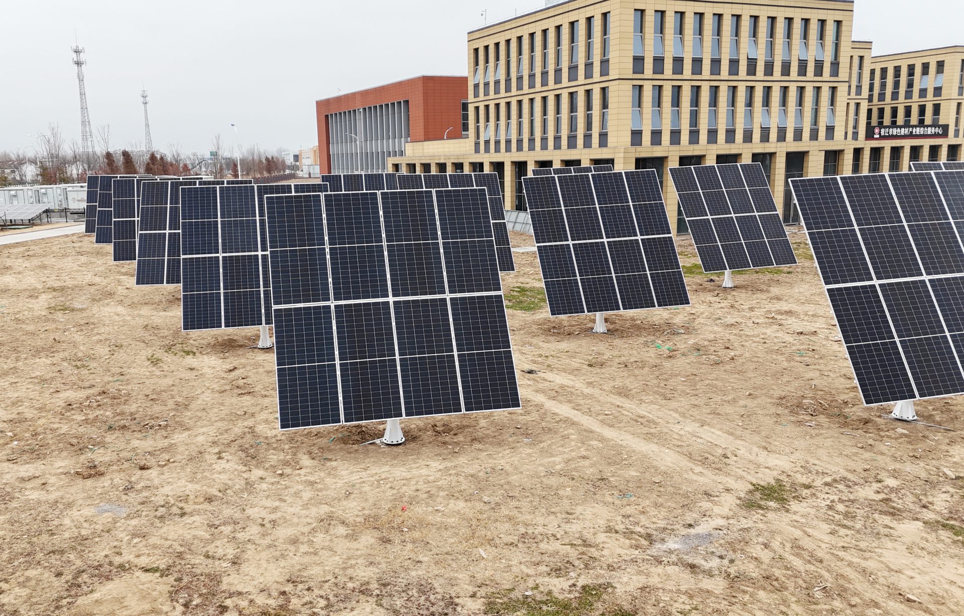
Eight scenes explain one eight-module dual-axis tracking power station: 8 × 620 W PV modules (2.3 × 1.1 m) with a nominal capacity of 4.96 kWp, dual-motor azimuth and tilt drive, 176 original CAD parts in 9 assembly groups, an SDE7A slew drive, eight native purlins and horizontal / tilt limit interlocks, closing on an exploded view of the whole station.
01 Overview
SZGZ-X
Our in-house solar tracking racking is different from fixed racks and single-axis trackers. It adjusts azimuth and tilt at the same time, keeping the modules at the best angle to the sun all day. Load-bearing structure, dual-axis drive, position feedback, control strategy, safety protection and cloud O&M make up six parts that work together as one complete solar tracking system.
- PV modules carried
- 8-24pcs
- Energy yield gain
- 30%↑
- O&M cost reduction
- 80%↓
- Module array8 × 620 W · 4.96 kWp
- Column & baseslew plane at 2.60 m
- Slew driveSDE7A · dual motor
02 Dual-Axis Tracking
Azimuth Slew + Tilt Motion
Powered by the SmartTrack™ 3.0 tracking algorithm: astronomical calculation and edge computing work together to stay locked on the sun's path; local irradiance and weather data correct the aim in real time, and tracking continues even under overcast diffuse light, with no grid power needed. Average annual yield is up 30%, and the winter peak gain can exceed 50%.
- Tracking accuracy
- ±0.5°
- Azimuth slew
- ±180°
- Tilt travel
- 0–85°
03 Slew Drive Assembly
Slew Drive Assembly
The slew mechanism ties drive, reduction and bearing support together on the azimuth axis, turning the upper array horizontally to follow the sun's azimuth angle.
- Slew drive
- SDE7Adual motor
- Drive assemblies
- 2motor barrels
- Slew plane height
- 2.60m
- Slew driveSDE7A · drive · reduction · bearing
04 Tilt Output
Tilt Output
The tilt motor turns the array about its native horizontal axis through the output plate and the round-shaft frame; eight native purlins and four angle beams carry the module load back to the tilt axis, with the travel range held by the tilt limit.
- Tilt drive
- SDE7Aoutput end
- Tilt demo range
- 0–65°
- Native purlins
- 8pcs
- Tilt outputSDE7A · upper rotating end
05 Limits & Interlocks
Limits & Interlocks
One horizontal and one tilt limit bracket with two trigger paddles each, plus five M8 limit switches: the array stops when it reaches a travel boundary, and the azimuth and tilt ranges are held by the mechanism itself.
- Horizontal limit
- 1set
- Tilt limit
- 1set
- Limit switches
- 5pcs · M8
- Limits & interlockshorizontal / tilt limits · 5 M8 switches
06 Extreme Conditions
Extreme Weather Protection
Cloud early warningAuthoritative weather data looks 72 hours ahead at severe conditions so protection can be staged in advance.
Edge fast responseOn-board sensors monitor at millisecond resolution and automatically trigger high-wind and heavy-snow protection modes.
Hardened hardwareLevel-12 wind rating, reinforced snow load, wide-temperature components and three-stage lightning protection.
07 Global Smart Cloud Platform
Global Smart Cloud Platform
See the whole fleet on the desktop dashboard, check it anywhere from the App, with monitoring and control in one place. Equipment, generation, alarms and control cover the full plant O&M workflow and cut blind site inspections.
08 Exploded View
Structure, exploded
Nine factory groups stack up above the load-bearing column: the column-cap mount with its level stops, the dual-axis drive with its limit sensors, the tilt output coupling, the round-tube frame with its M8 locks, the four corner beams, the eight purlins, then the eight modules. The control box lifts off to one side. Every group ships pre-assembled — on site the station bolts together around the column.
- Major assemblies
- 9groups
- Original CAD parts
- 176pcs
- Fasteners & joints
- 121pcs
- Load-bearing columnfixed to the cap plate
- Dual-axis driveSDE7A · azimuth + tilt
- Module array8 × 620 W · 4.96 kWp
- Tilt outputSDE7A · upper rotating end